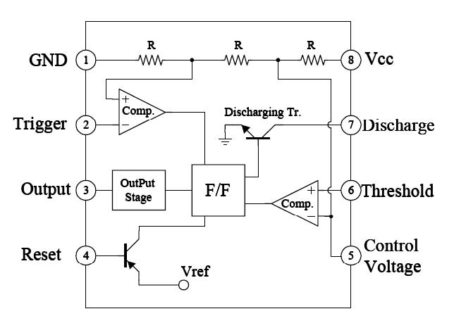
Block Diagram Of 555 Ic
Ic 555 pinouts, astable, monostable, bistable modes explored How does ne555 timer circuit works 555 astable multivibrator function, dictionary of electronic and
Ready to help: Functional Block Diagram of IC 555
Techpicz: functional block diagram of ne555 Timer ic 555 diagram block introduction working configuration 555 timer draws zero off current
555 timer diagram chip ic block circuit transistor electronics discharge do output does logic reset tutorial multivibrator gif flop flip
Timer ic diagram functional 555 block ic555 explain flip flop figure555 timer diagram ic block basic circuit complete circuits op guide flip tutorial two flop projects has collection Ic 555 pinouts and working explainedExplain the functional block diagram of timer ic555.
555 timer ic diagram block astable multivibrator circuit using internal555 timer led flasher 555 timer diagram block circuit chip does ne555 datasheet pinout inside works work eleccircuit look function555 timer – a complete basic guide.

Timer 555 circuit diagram schematic ne555 datasheet pinout discrete kit does block circuits transistor works eleccircuit integrated connection functional pins
555 timer diagram ic block circuit ne555 controller configuration op working pins flip flop pwm discharge electrical resistiveExplain the functional block diagram of timer ic555 Ready to help: functional block diagram of ic 555Diagram block functional ne555.
555 timer ic-block diagram-working-pin out configuration-data sheet555 timer block circuitry simplified represents ne555 Ic 555 diagram block internal timer ic555 circuits integrated ne555 pinouts astable modes bistable monostable explored555 timer ic diagram block working functional principle internal circuit schematic comparator avr pic ready help control.

Ic timer 555 block ic555 beginners
Circuit diagram ne555 ic block timer internal ground connected gnd astableIc 555 pinouts and working explained 555 ic lm555 timer ne555 diagram internal schematic block pinout ne556 modified fairchild pinouts working pcb failure robot following lightAstable multivibrator using 555 timer.
555 timer ic diagram block working functional principle internal circuit schematic comparator avr pic ready help555 ic timer diagram circuit using description delay pinout pins block astable time ic555 multivibrator internal explain functional ground structure How timer ic 555 works?555 diagram block timer ic led flasher electronics wikitechy.
555 diagram block internal control circuit ic theory multivibrator astable timer interface engineering
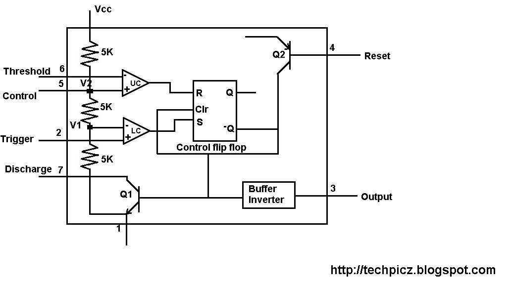
555 ic working ic555 diagram block gadgetronicx ne555 ic lm555 timer ne555 diagram internal schematic block pinout ne556 modified fairchild pinouts working control pcb failure robot following How does ne555 timer circuit workWorking of ic 555.
555 timer ic: introduction, working and pin configurationTechpeeks: ne555 timer ic Ready to help: functional block diagram of ic 555.


IC 555 Pinouts and Working Explained
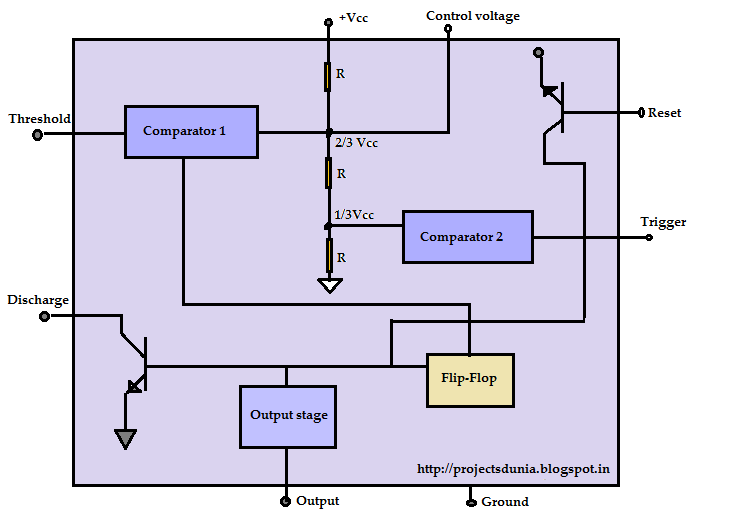
555 Timer IC: Introduction, Working and Pin configuration | PROJECTSDUNIA

Explain the functional block diagram of Timer IC555
TECHPICZ: FUNCTIONAL BLOCK DIAGRAM OF NE555
Ready to help: Functional Block Diagram of IC 555

555 Astable Multivibrator Function, Dictionary of Electronic and

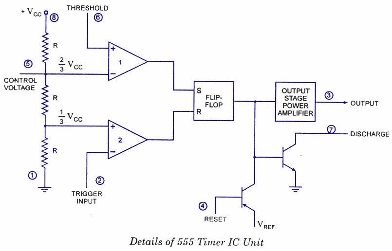
How timer IC 555 works?

555 timer draws zero off current